A - AOI CASE ACK EN, A - Reply Open, A - 1 Hour Delay rslv, AOI - New CSAT Sent, LOCKED
Current case
Customer issue
Good morning, I am seeking to gain a deeper understanding of the following inspection item: electrode wettability in comparison to land wettability. What specific criteria should be considered in this evaluation? With respect to this component, it is noteworthy that an assessment of its electrode wettability frequently results in a warning indicating very low solder levels. J. Luis Andres AOI Supervisor P [phone] ext 231 ITAR Disclaimer: This message, including any attachments, is for the sole use of the intended recipient(s) and may contain confidential and privileged information. Any unauthorized review, use, disclosure or distribution is prohibited. ITAR CONTROLLED This correspondence may contain Technical Data whose export is restricted by the Arms Export Control Act (Title 22, U.S.C., Sec 2751, et seq.). Violations of these export laws are subject to severe criminal penalties. This data may not be resold, diverted, transferred, transshipped, made available to a foreign national by any means.
Conversation
Engineer and customer thread
4 messages
OA
Omron Application EngineerOmron reply | May 14, 2026 at 2:18 PM
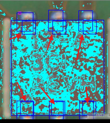
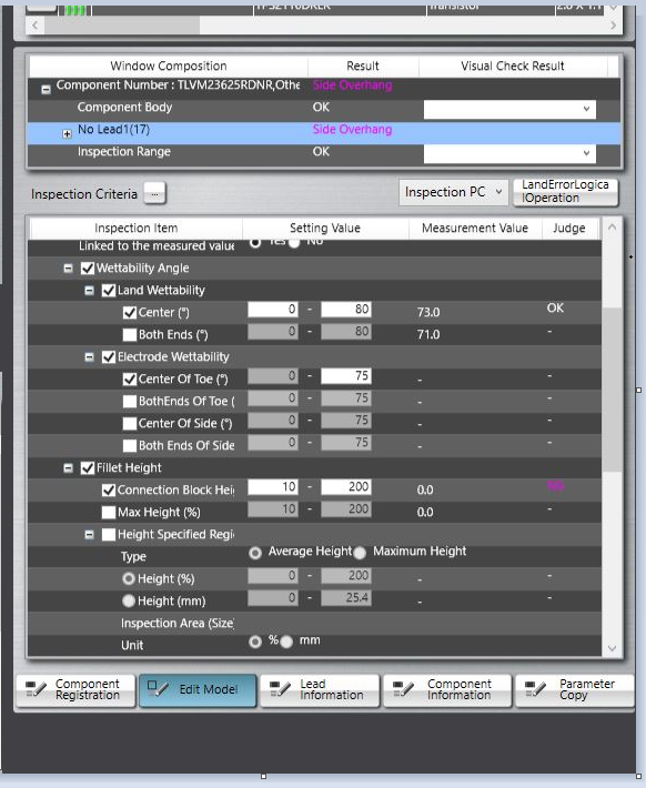
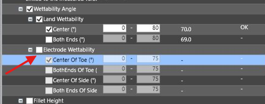
Good afternoon Luis, Electrode wettability and land wettability are related, but they evaluate different areas of the solder joint. Land wettability evaluates how well the solder wets/spreads across the PCB land/pad area. This inspection is focused on the solder condition on the land side. If solder does not spread sufficiently on the land, or if exposed land remains, this can indicate insufficient wetting or insufficient solder coverage. Electrode wettability evaluates how well the solder wets to the component electrode/termination. This inspection is focused on the solder connection at the component side, such as the electrode toe/end or side area. The system checks the wetting angle between the solder and the component electrode. If the solder joint to the electrode is not sufficient, the system may report an electrode wettability warning or fault. The Omron manual describes this type of result as occurring when the solder joint with the electrode is not sufficient, when solder wetting height is low, or when the solder joint width/side wetting is not sufficient. For this type of evaluation, the main items to confirm are: Actual solder condition Confirm whether there is enough solder volume at the component termination. Confirm whether the solder is visibly wetting up to the electrode/toe area. A low solder condition can pass land wettability but still show concern at the electrode if the solder does not sufficiently contact or climb the component termination. Land window and electrode window position If the land window, electrode window, electrode tip, or electrode side extraction is not aligned correctly, the system may evaluate the wrong area. The teaching manual specifically lists incorrect land window position, incorrect component/electrode extraction, incorrect electrode tip extraction, incorrect electrode side extraction, and incorrect electrode window size as possible causes for wetting errors. Color/fillet extraction settings These inspections are based on solder color detected in the land window. If the fillet excluded color or solder/metal color extraction is not set correctly, the system may not correctly recognize the solder area. This can cause a false low-solder or wettability warning. Inspection criteria Electrode wettability includes items such as Center of Toe, Both Ends of Toe, Center of Side, and Both Ends of Side. The logic manual indicates that a wettability error can be output if the joint angle between the electrode and solder is outside the set criteria, or if solder is not detected in the inspection range. One additional item we noticed from the screenshot is that Electrode Wettability is not currently enabled for inspection. Only Land Wettability – Center appears to be selected. Since this is a QFN / no-lead style component, the setup of the “lead/electrode” extraction boxes is still important because the system uses those boxes to determine the correct solder/electrode relationship at the edge of the package. In the image provided, several of the blue lead/electrode boxes do not appear to be centered correctly within the land pad boxes. Before adjusting inspection thresholds, we recommend manually correcting the lead/electrode box positions in the Inspection Registration tab so they are centered on the pads and aligned to the package edge. If these boxes are shifted, the system may evaluate the wrong area and report low solder or wettability concerns even when the actual solder joint may be acceptable. Does this help answer your questions? Let us know, thanks.
C
CustomerCustomer reply | May 15, 2026 at 12:07 PM
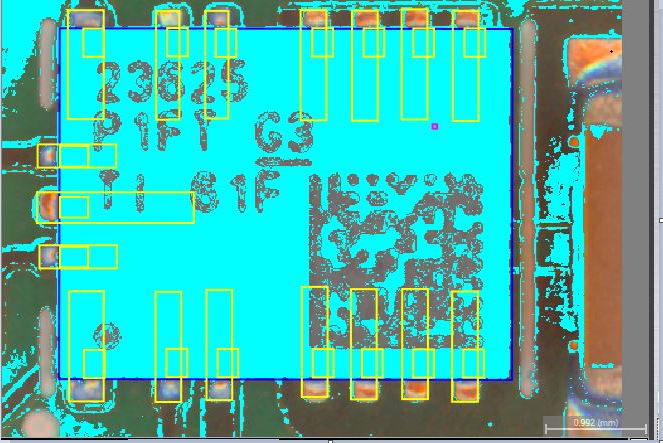
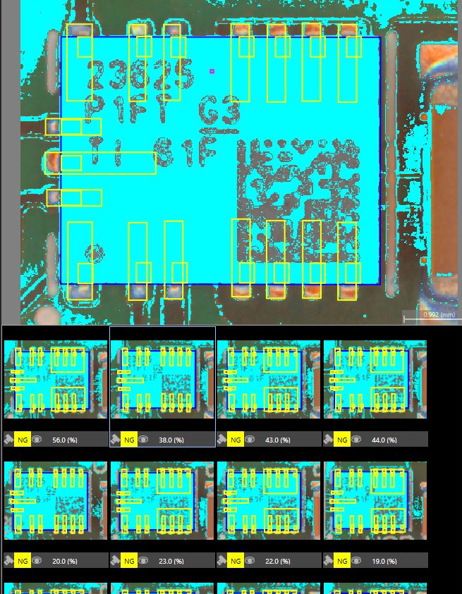
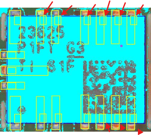
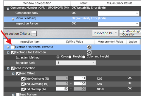
Thank you for your well-written explanation, Jeremiah. I also had a couple more questions #1 I noticed that two of the lands were larger than the others, so I edited the component in "Inspection Registration." However, the changes only applied to the one I modified. How can I update the remaining lands at the same time, or do I need to make the changes individually? [cid:a0a32a7d-5ce3-4eae-9da3-ce1775111a72] #2 After adjusting the lands and solder inspection. My leads keep shifting to the side. How can I prevent this from happening , and have it checked in the center where the solder should be located [cid:931cbed8-658e-4c6a-90fb-51553e89f85a] #3 I believe this issue is related to the side overhang. While I understand that this is a no-lead component, there are certain areas where solder is present on the land. I would appreciate it if you could provide a reading, if possible. Could you please check if the settings are configured correctly or suggest a better option I could implement? [cid:7909c3c9-a745-4f03-8799-ce2c23d15835] J. Luis Andres AOI Supervisor P [phone] ext 231 ________________________________
Omron Application EngineerOmron reply | May 15, 2026 at 2:10 PM
Hello Jose, For your question #1, I've attached a video to show you how to fix that issue. For #2 Since that QFN has no leads to lock onto, I would disable the Electrode Horizontal Extraction. This will make the software "trust" you as the programmer, that those leads will always be there and not bend to one side or the other, or lift. This case, no lead...so you can disable this. For #3, your side overhang will resolve once you follow #2 fix above. Below, you can see these leads are technically outside of the bigger land box. Please disable horizontal extraction and test. You'll see :) Hope this helps.